Product List
Product Description
Guide Bushing Center Hanged Type˙Cage material/POM ˙Needle type of ball retainer ˙Guide post and bushing/S3K3 Download

- Product Specification
- Product Characteristics
Ex Order.
HGNZC - 12 - 50
*Needle ball retainer for this model are available as a single item.((For complete details, please download the catalog)
| HGNZC | 12 | 50 |
|---|---|---|
| | | | | | |
| Model | External diameter of Guide Post D | Length of Guide Post L |
Feature
- The rigidity of the line contact rolling pins provide rigidity over 10 times greater.
- Straightness exceeds 2 times.
- Rolling pins distribute pressure, extending service life.
- Low vibration enables low pre-loading.
- High precision, repeatability exceeds 3 times.
| Component | ||
|---|---|---|
| Name | Material | Hardness |
| ① Guide Post | SKS3 | 60~62 HRC |
| ② Guide Bushing | SKS3 | 60~62 HRC |
| ③ Needle Roller Retainer | Needle(POM): SUJ2 | - |
| Retainer: Super Engineering Plastic | ||
| Optional Part | ||
| ④ Fixed Stopper | S45C | - |
| ⑤ Spring | SWP-B | |
STEP.1
Please select the material of the column, the outer diameter of the column D and select the length of the guid post L.

| D | L | ① Guide post | ② Guide bushing | |||||||||
|---|---|---|---|---|---|---|---|---|---|---|---|---|
| Effective stroke | D1 | H | PCD | M×ℓ | D3 | D2 | PCD1 | L1 | H1 | ød1 | ||
| 12 | 50~120 | 20 | 30.0 | 7.0 | 22 | - | 40 | 23 | 32.0 | 40 | 7.0 | 4.4 |
| 16 | 80~140 | 20 | 36.0 | 9.0 | 27 | - | 48 | 30 | 39.5 | 40 | 9.0 | 5.5 |
| 20 | 80~140 | 16 | 41.0 | 9.0 | 31.5 | - | 56 | 37 | 47.5 | 60 | 9.0 | 5.5 |
| 25 | 100~210 | 16 | 48.0 | 12.0 | 37 | - | 67 | 44 | 56.0 | 70 | 12.0 | 6.5 |
| 28 | 100~210 | 18 | 51.0 | 12.0 | 40 | - | 70 | 47 | 59.0 | 75 | 12.0 | 6.5 |
| 30 | 100~210 | 20 | 53.0 | 13.0 | 42 | - | 73 | 50 | 62.0 | 78 | 13.0 | 6.5 |
| 35 | 120~220 | 24 | 58.0 | 13.0 | 47 | 10×25 | 82 | 58 | 71.0 | 86 | 13.0 | 6.5 |
| 40 | 120~220 | 28 | 70.0 | 15.0 | 56 | 12×30 | 97 | 68 | 83.5 | 92 | 15.0 | 8.5 |
| 50 | 160~250 | 28 | 82.0 | 15.0 | 68 | 12×30 | 107 | 78 | 93.5 | 96 | 15.0 | 8.5 |
| 60 | 160~250 | 28 | 97.0 | 18.0 | 80 | 14×30 | 134 | 95 | 117.0 | 120 | 18.0 | 11.0 |
| ③ Needle Roller Retainer | ④Fixed stopper | ⑤ Spring | ||||||
|---|---|---|---|---|---|---|---|---|
| RL | ød | L1 | Amount of Needle | D3 | D4 | L3 | M | SL |
| 30 | 2.0 | 4.8 | 45 | - | - | - | - | 30~100 |
| 30 | 2.0 | 6.8 | 24 | 17.5 | 14.4 | 14 | 6 | 30~100 |
| 52 | 2.0 | 6.8 | 57 | 21 | 18 | 23 | 8 | 40~100 |
| 62 | 2.0 | 7.8 | 69 | 24 | 23 | 28 | 8 | 55~125 |
| 66 | 2.5 | 7.8 | 57 | 30 | 25.5 | 30 | 8 | 55~145 |
| 68 | 2.5 | 7.8 | 57 | 32 | 27.5 | 31 | 10 | 50~160 |
| 74 | 2.5 | 9.8 | 69 | 37 | 32.5 | 34 | 10 | 65~175 |
| 78 | 3.0 | 9.8 | 75 | 43 | 38 | 36 | 12 | 70~170 |
| 82 | 3.0 | 11.8 | 78 | 52.5 | 47.5 | 38 | 12 | 90~200 |
| 116 | 4.0 | 13.8 | 84 | 64.5 | 57.5 | 54 | 14 | 100~200 |
Flange type Z-axis guide: the most suitable for elevating stage
Shaft diameter ∅60~80
Inspection Devic
High rigidity and low vibration make the camera statically determinate quicker, and lead to shorter cycle time.
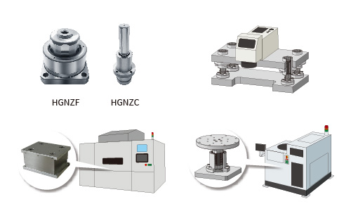
Precision Z stage for the exposure equipment
Accuracy improvement enables sub-micron order positioning.
stage for the prober
Higher guide rigidity reduces the deflection caused by the offset load on the stage.
Installation Method
1、 Processing of installation holes for Guide posts and bushing
Tap 4-ØZPP, ØZBP at the post & the bush installation plate. Confirm the PCD and PCD1 according to the product size.
| Product Name | Screw Hole |
|---|---|
| HGNZF·HGNZC 12 | M4 |
| HGNZF·HGNZC 16 | M5 |
| HGNZF·HGNZC 20 | |
| HGNZF·HGNZC 25 | M6 |
| HGNZF·HGNZC 28 | |
| HGNZF·HGNZC 30 | |
| HGNZF·HGNZC 35 | |
| HGNZF·HGNZC 40 | M8 |
| HGNZF·HGNZC 50 | |
| HGNZF·HGNZC 60 | M10 |
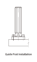
2、Post installation
- Determine the counter mark direction for easy recognition.
- Fix the post to the installation hole of the plate with the specific bolts.
- The post perpendicularity must be checked (0.01mm/100mm or less)
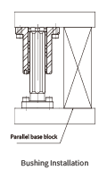
3、Bush installation
- Combine the post and the bush. Make sure the counter marks and the specific numbers are correspondent.
- Place the parallel base block on the plate of the post side, put the plate of the bush side on it and fit it to the installation hole.
- Fix the bush to the plate with the specific bolts.