Shaft diameter 6-50 mm ・ For high-end automation composite loads ・ Premium alloy steel (SCM440/SUJ2) ・ 7 surface treatment options
- Product Specification
- Product Characteristics
- Why you must choose HEADWAY
Product Specifications: Explanation of Nominal Model Codes
To ensure accuracy in selection and procurement, please refer to the following nominal model coding principles for interchangeable ball spline sets:
Coding Example: KLF 016 T4 N S 500 P2 - B2 M + N3 N3
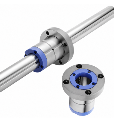
- Spline Nut Type: KLF (Round Flange Type)
- Nominal Shaft Diameter: Standard supply 006, 008, 010, 013, 016, 020, 025, 030, 040, 050 (Unit: mm)
- Number of Ball Rows: T2 (2 rows of balls), T3 (3 rows of balls), T4 (4 rows of balls)
- Spline Shaft Accuracy: Q (Commercial Grade), N (Normal Grade), H (High Grade), P (Precision Grade), SP (Super Precision Grade), UP (Ultra Precision Grade)
- Spline Shaft Type: S (Solid Spline Shaft), K (Standard Hollow Spline Shaft), N (Thin-Walled Hollow Spline Shaft), M (Special Custom Hollow Shaft)
- Spline Shaft Length: Fill in according to customized cutting length requirements (Unit: mm)
- Preload Grade: P0 (With Clearance), P1 (No Preload), P2 (Light Preload), P3 (Medium Preload)
- Number of Spline Nuts: Omitted for a single spline nut; marked as B2 if two spline nuts are configured on a single shaft.
- Main Material: C (Carbon Steel, standard material code can be omitted), M (Stainless Steel)
- Surface Treatment (Nut/Shaft): S (Omitted for standard untreated), B1 (Black Oxide), N1 (Chrome Plating), P (Phosphating), N3 (Electroless Nickel Plating), N4 (Cold Electroplating), N5/N6 (Nano Coating)
KLF Series Dimensions and Performance Specification Table
Standard KLF series specifications are available in stock for all sizes. Below are the detailed dimensions and torque/load performance parameters:
| Nominal Model No. | Shaft Dia. d (mm) | Ball Rows | Outer Dia. D (mm) | Total Length L (mm) | Flange Dia. A (mm) | Flange Thick. B (mm) | Dynamic Torque Ct (N·m) | Static Torque Cot (N·m) | Dynamic Load C (kN) | Static Load Co (kN) | Shaft Weight (kg/m) |
|---|---|---|---|---|---|---|---|---|---|---|---|
| KLF06T2 | 6 | 2 | 14 | 22 | 30 | 6 | 4.51 | 7.44 | 1.34 | 2.2 | 0.22 |
| KLF06T3 | 6 | 3 | 14 | 22 | 30 | 6 | 6.31 | 10.43 | 1.74 | 3.3 | 0.22 |
| KLF08T2 | 8 | 2 | 16 | 24 | 32 | 8 | 5.88 | 9.71 | 1.34 | 2.2 | 0.39 |
| KLF08T3 | 8 | 3 | 16 | 24 | 32 | 8 | 8.23 | 13.58 | 1.74 | 3.3 | 0.39 |
| KLF10T2 | 10 | 2 | 21 | 31 | 42 | 9 | 15.87 | 22.04 | 2.79 | 3.89 | 0.60 |
| KLF10T3 | 10 | 3 | 21 | 31 | 42 | 9 | 22.22 | 30.86 | 3.63 | 5.83 | 0.60 |
| KLF13T2 | 13 | 2 | 24 | 35 | 44 | 9 | 28.32 | 38.61 | 3.88 | 5.29 | 1.03 |
| KLF13T4 | 13 | 4 | 24 | 35 | 44 | 9 | 49.56 | 54.05 | 5.10 | 7.93 | 1.03 |
| KLF16T2 | 16 | 2 | 31 | 47 | 51 | 10 | 46.75 | 72.81 | 5.34 | 8.32 | 1.56 |
| KLF16T4 | 16 | 4 | 31 | 47 | 51 | 10 | 81.81 | 127.42 | 7.04 | 12.88 | 1.56 |
| KLF20T2 | 20 | 2 | 35 | 53 | 58 | 10 | 77.42 | 118.48 | 7.10 | 10.86 | 2.44 |
| KLF20T4 | 20 | 4 | 35 | 53 | 58 | 10 | 135.48 | 207.34 | 9.20 | 14.10 | 2.44 |
| KLF25T4 | 25 | 4 | 42 | 70 | 65 | 13 | 215.50 | 421.50 | 9.82 | 15.61 | 3.80 |
| KLF30T4 | 30 | 4 | 47 | 77 | 75 | 13 | 296.55 | 616.71 | 11.37 | 19.40 | 5.49 |
| KLF40T4 | 40 | 4 | 64 | 100 | 100 | 19 | 1032.63 | 1725.29 | 29.12 | 39.52 | 9.69 |
| KLF50T4 | 50 | 4 | 80 | 121 | 124 | 20 | 1762.92 | 2982.63 | 40.04 | 55.03 | 15.19 |
Note: Basic engineering conversion criteria: 1 kN ≈ 102 kgf; 1 N·m ≈ 0.102 kgf·m
- Zero Backlash in Rotational Direction & High Rigidity: Utilizing a design of 2 to 4 opposing rows of balls with a 40° contact angle, combined with appropriate preload adjustment, rotational backlash can be reduced to zero. The displacement under the same torque is only half of that without preload, and the rigidity is increased by more than 2 times, ensuring precise indexing even under frequent forward/reverse rotations and alternating load operations.
- Large Load Capacity & Lightweight, Compact Structure: Due to the large contact area of the Gothic arch deep grooves, the rated load that the ball spline can withstand under the same shaft diameter is more than a dozen times that of traditional linear ball bushings. This allows the overall mechanism design to significantly reduce space and become more compact, providing safety and high durability even under cantilever loads or large torque.
- Premium Alloy Material & Ultimate Wear Resistance: The shaft body and spline outer cylinder are meticulously crafted from high-grade alloy steel (such as SCM440/SUJ2). Through professional heat treatment and quenching processes, the surface hardness of the raceway reaches HRC 58~62, ensuring ultimate wear resistance and a long operational lifespan.
- Easy Assembly & Non-detachable Steel Balls: The interior of the outer cylinder features a special circulation retainer structure. Even if the spline outer cylinder is completely detached from the shaft during cantilever setups or maintenance/warranty periods, the steel balls will not fall out. This makes the initial assembly, internal inspection, cleaning, and maintenance of the equipment extremely convenient and safe.
- Highly Customizable Post-Processing: The entire series supports highly flexible shaft-end post-processing services. Whether it is a precision stepped shaft, external thread, standard/special keyway, or precision drilling, Headway can precisely customize it based on the customer's blueprints, helping to shorten the assembly timeline for automation equipment.
- Widely Applicable to High-End Precision Industries: Perfectly suited for fields such as semiconductor equipment, SCARA industrial robots, automated assembly lines, precision measuring instruments, optoelectronic panel handling systems, and medical automation.
HEADWAY presents you with superior quality, firm commitment, and a spirit of partnership. As a manufacturer of automation and mold components, we possess deep knowledge of automation and mold technology, continuously innovating and improving to ensure outstanding performance and reliability.
On the official HEADWAY website, you can not only browse product catalogs but also understand that each product represents our commitment to quality and our responsiveness to customer needs. We rigorously control the manufacturing process, utilizing high-quality materials and precision machining to ensure that every product meets your expectations.
(1).Streamlined Production
(2).No minimum order quantity, we can produce even one.
(3).100% inspection - From production to inspection equipment, all steps are completed by HEADWAY.
(4).Accept custom processing inquiries based on provided drawings.
(5).For product issues and subsequent after-sales service, we provide personalized assistance for you.