

Space Constraints vs. Rigidity First? A Comprehensive Guide to Optimal Application Scenarios for KLF and KLT Ball Splines
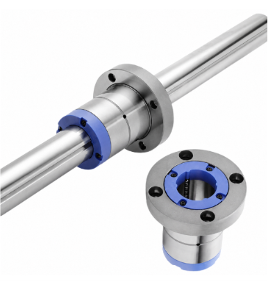
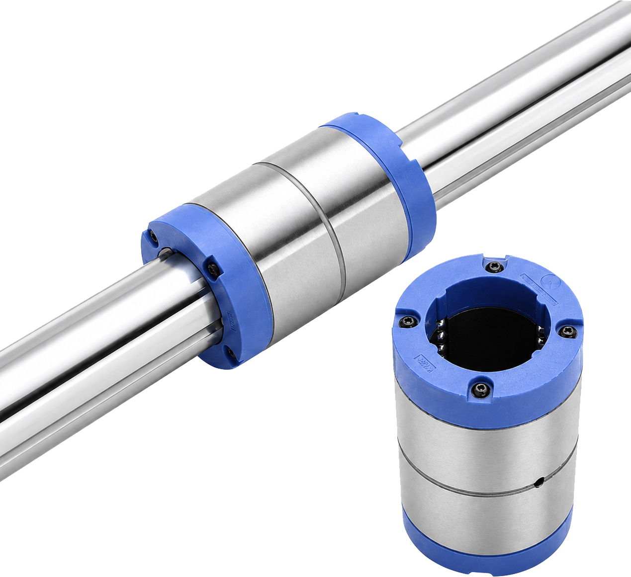
In the mechanical design of high-speed semiconductor sorting or multi-axis dispensing systems, engineers frequently face a critical trade-off: minimizing the center-to-center pitch between shafts while suppressing cantilever inertia-induced micro-vibrations during high-frequency, rapid start-stop cycles. Ball splines enable both linear sliding motion and zero-backlash torque transmission along a single shaft. KLF and KLT represent two primary solutions specifically tailored to distinct mechanical mounting interfaces.
KLF Round Flange Type: The Premier Choice for Overturning Moment Resistance and Maximum Rigidity
- Structural Characteristics: Features an integrated circular flange with mounting bolt holes machined on the end face, allowing direct fastening to the machine base.
- Load-Bearing Advantages: The wide flange supporting surface evenly distributes overturning moments, maintaining exceptional dynamic rigidity under frequent forward/reverse cycles and high acceleration/deceleration.
- Recommended Applications: Ideal for long cantilever or lateral load conditions, such as SCARA robot Z/θ axes, semiconductor wafer pick-and-place cantilevers, and flat panel display transfer mechanisms.
KLT Cylindrical Type: The Ideal Solution for Confined Spaces and High-Density Multi-Axis Layouts
- Structural Characteristics: Features a compact, flangeless cylindrical body that transmits torque by fitting standard outer cylinder keyways (b × t) into housing bores.
- Space Advantages: The outer cylinder sits completely flush with the mounting bore, eliminating flange edge interference and minimizing multi-axis installation footprints to the extreme.
- Recommended Applications: High-density arrangements such as biomedical micro-dispensing equipment (closely aligned multi-channel sampling needles), optical measurement probe elevation mechanisms, and compact electronic surface-mount devices.
Both series feature 40° Gothic arch ground raceways and heat-treated alloy steel (hardness reaching HRC 58–62), delivering load capacities more than ten times higher than conventional linear bushings. Furthermore, both incorporate internal ball-retaining circulation mechanisms. Therefore, model selection depends entirely on the machine's spatial layout and mounting interfaces.
Frequently Asked Questions (FAQ)
Q1: Under the same shaft diameter, is there any difference in rated load and torque transmission capacity between the two?
A1: Under identical shaft diameters and ball circuit configurations (e.g., a 16 mm diameter shaft paired with a T4 four-row ball design), the internal contact angles and raceways are identical. Consequently, basic dynamic and static load ratings as well as torque capabilities are the same. The only difference lies in the load support characteristics of the external mounting housing.
Q2: How should engineers determine the selection boundary when arranging multiple shafts in close parallel?
A2: If the center distance between adjacent shafts is smaller than the sum of the flange outer diameter and the tool clearance required for fastening, the KLT cylindrical type should be selected directly. If the mechanism provides adequate end-face clearance and the cantilever end is subjected to substantial loads, the KLF type is recommended to secure base rigidity.
Q3: During on-site maintenance, will the steel balls fall out when the spline outer cylinder is removed from the shaft?
A3: No. Both KLF and KLT outer cylinders are equipped with a specialized circulation retainer structure. Even when the outer cylinder is completely detached from the spline shaft, the steel balls will not fall out, significantly enhancing assembly and maintenance convenience.
More Information
The content of this article is based on a specific case study. Actual application results may vary depending on industry characteristics, specification requirements, and operating conditions. The information provided is for reference only.


