

Loose One Fin, Tight the Next? The Pitfall of Incorrect Shaft-Hole Fit Tolerances—No Amount of Tightening Can Save It
Same Blueprint, Same Machine, Yet Retaining Rings Are Alternatingly Loose and Tight
The procurement department reported a recurring issue: using the exact same drawing and sourcing from the identical vendor, the latest batch of retaining rings felt inconsistent when mounted onto the shaft. Some were so tight they required tools to be pushed in, while others were so loose they could be rotated with a bare finger. Inspection reports indicated that all hole diameters fell well within the limits specified on the drawing ; the parts themselves did not exceed the tolerance zones.
The root cause lay in the engineering drawing, which merely specified "Diameter Φ20mm" without designating a fit tolerance class. Consequently, while every single part was technically "conforming," the actual fit tightness drifted with the upper and lower limits of the tolerance zone. This forced the assembly line to test-fit parts piece by piece and adjust them purely by feel.
The Core Logic of Fit Tolerance: Tolerance Zones Dictate Tightness, Not Just Dimensions
A single dimension callout (such as "Φ20mm") only regulates the size of the individual part itself ; it does not govern the relationship or tightness between the part and its mating component. Within the same tolerance zone, if the shaft is machined to its upper limit and the hole to its lower limit, the cumulative variance in tightness can far exceed expectations. This is precisely why "parts conform, but assembly is inconsistent".
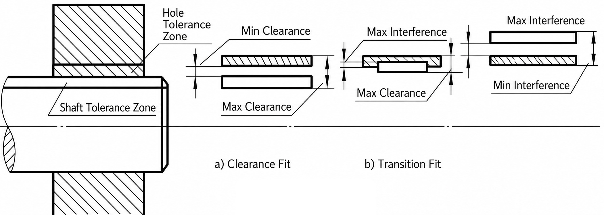
The correct practice is to simultaneously specify the fit tolerance classes for both the shaft and the hole on the drawing. This elevates locking and fastening from "post-assembly adjustment by feel" to "locking down the tightness range during the design phase". The two most common and reliable types of fits are Clearance Fits and Transition Fits.
Clearance Fit
The dimension tolerance zone of the shaft falls entirely below that of the hole. Once assembled, a clearance is guaranteed to exist between the shaft and the hole. Common combinations include H7/g6 and H7/f7. The size of the clearance is determined by the combination of tolerance classes. The tighter the selected class (such as g6), the smaller the clearance and the higher the positioning accuracy. Conversely, the looser the class (such as f7), the larger the clearance, which facilitates rotation or sliding. This type of fit is ideal for applications requiring relative motion, frequent disassembly, or reliance on a lubricating oil film. Furthermore, assembly requires no force, allowing for repeated disassembly without damaging the components.
Transition Fit
The tolerance zones of the shaft and the hole partially overlap. Once assembled, the fit may result in either a slight clearance or a slight interference, depending entirely on where the specific batch of parts falls within their tolerance zones. Common combinations include H7/k6 and H7/n6. This type of fit typically requires manual pressing or light tapping for assembly. It offers high positioning accuracy and prevents relative slippage. Additionally, the closer the dimensional tolerance shifts toward the interference end (such as n6), the stronger the holding force, effectively preventing axial displacement. Conversely, shifting toward the clearance end (such as k6) retains a small margin for fine-tuning, though major adjustments become difficult once positioned.
The Prerequisite for Choosing the Right Fit: Drawings Must Be Complete
It is critical to note that merely labeling the fit class code (such as H7/g6) is still insufficient to fully lock in the results[cite: 53]. Drawings must explicitly state the upper and lower dimensional tolerance limits for both the shaft and the hole[cite: 54]. Engineers should determine whether to use a clearance or transition fit based on rotational speed, vibration, and disassembly frequency[cite: 55]. The vendor can then strictly control the manufacturing process according to the tolerance zones, ensuring a consistent assembly feel for every batch of parts[cite: 56].
Frequently Asked Questions (FAQ)
Q1: Can clearance fits and transition fits be mixed on the same shaft?
A: Yes. Different segments of the same shaft can be assigned different fit tolerances based on the functional requirements of individual components. For instance, a rotating section can utilize a clearance fit, while a fixed, locating section can adopt a transition fit—provided that the dimensional tolerances for each segment are clearly and distinctly marked on the drawing.
Q2: Once a transition fit is assembled, can it be disassembled for readjustment?
A: It is not recommended. Disassembling and reassembling a transition fit will gradually scratch the mating surfaces and alter the actual tolerance, rendering the tightness unreliable upon reassembly. If an application demands repeated disassembly and adjustment, it is advisable to switch to a clearance fit.
Q3: What does a smaller number in a tolerance class mean (e.g., g6 vs. g7)?
A: The number represents the tolerance grade (IT grade). The smaller the number, the narrower the tolerance zone, which demands higher machining precision and incurs greater production costs. A larger number means a wider tolerance zone, which lowers manufacturing costs but reduces the consistency of the fit tightness. You should select a grade that is sufficient for your practical needs, rather than assuming that tighter precision is always better.
Q4: Why is the assembly tightness still inconsistent even though all parts are within the tolerance range?
A: This usually happens because the drawing only specifies a basic dimension without designating a fit tolerance class. As a result, the shaft and hole dimensions float freely within their respective tolerance zones, and the cumulative variance amplifies the difference in tightness upon assembly. It is recommended to first verify whether the drawing fully specifies the fit tolerances, rather than merely checking whether individual parts conform to a single dimensional range.
More Information


